10.10 Distributed Energy Resources function set
10.10.1 Overview
This function set provides an interface to manage distributed energy resources (DERs). There are two main types of client devices of this function set: generation and storage. Examples of the first type include fuel cells, intelligent solar inverters, and backup generation units. Examples of the second type include battery storage systems and electric vehicles (which may not be capable of discharging). Server devices of this function set include ESIs and premises energy management systems.
Servers host one or more DERPrograms, which in turn expose DERControl events to DER clients. DERControl instances contain attributes that allow DER clients to respond to events that are explicitly targeted at specific kinds of devices. A DERControl instance also includes scheduling attributes that allow DER clients to store and process future events. These attributes include start time and duration, as well an indication of the need for randomization of the start and/or duration of the event.
The IEEE 2030.5 DER client model is based on the SunSpec Alliance Inverter Control Model (SunSpec [B10]) which is derived from IEC 61850-7-420 [B4] and EPRI [B2].
10.10.2 Terminology and conventions
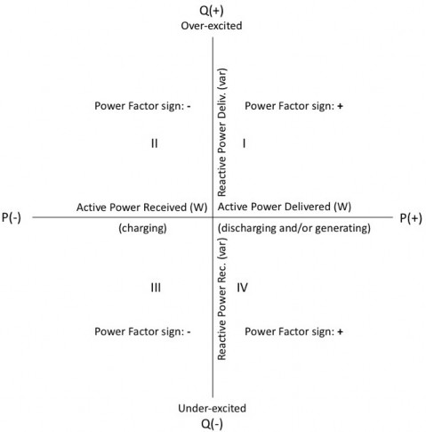
The terminology used to describe the IEEE 2030.5 DERControl interface is relative to the DER as a power producer. A DER described here as a generator delivers active ac power for consumption in the residence or the grid. By convention, a sub-meter connected at the DER accumulates positive energy usage when the DER is delivering active power. From the utility perspective, a DER operating in this mode may be viewed as a “negative load” and the premises aggregation meter will accumulate energy usage at a slowed or negative rate.
When the DER has attached storage, it is described here as a load and receives active power when in charging mode. It behaves like a generator and delivers active power when in discharging mode.
By convention, positive active and reactive powers flow in the same direction (here the reference direction is from the DER to the utility). When a DER is providing positive vars (i.e., behaving like an over-excited motor or generator) it is said here to be delivering reactive power (var).
In addition to the reference frame, the IEEE 2030.5 DER interface defines the power factor representation to avoid configuration mismatches. DER power factor settings representations consist of two elements: an unsigned value representing the ratio of active power to apparent power and an excitation. The excitation indicates whether reactive power is being injected (over-excited) or absorbed (under-excited).
It may be desirable to have different power factor settings when a DER is injecting active power and when it is absorbing active power. For this reason, the DER function set supports fixed power factor for both injecting active power and absorbing active power.
For measurement purposes, a power factor measurement is a single value that reflects the ratio of active power to apparent power. If a sign is present, it is the same as the active power sign. The sign of reactive power indicates the excitation (positive for over-excited and negative for under-excited).
These relationships are shown in Figure 3. At a given point in time, a DER may operate in any one of the four quadrants depending on its ability to deliver or receive active and reactive power.
Figure 3 —Active and reactive power flow directions as measured at the DER
10.10.3 List ordering
Table 50 —Distributed energy resources list ordering
Resource name | Primary key | Secondary key | Tertiary key |
DERProgram | primacy (ascending) | mRID (descending) | N/A |
DERControl and ActiveDERControl | interval.start (ascending) | creationTime (descending) | mRID (descending) |
DERCurve | creationTime (descending) | mRID (descending) | N/A |
DER | href (ascending) | N/A | N/A |
10.10.4 Application guidelines/behavior
10.10.4.1 DERProgram
Multiple programs can be created to target different types of devices or to offer different types of incentives. A DER client will typically discover its associated DERProgramList through Function Set Assignments.
DERProgram server devices SHALL be capable of internally storing and supporting at least one DERProgram instance. DERProgram server devices SHOULD be capable of internally storing and supporting three unique DERProgram instances. Each DERProgram instance SHALL be uniquely identified by an mRID.
DER client devices SHALL be capable of internally storing and supporting at least one DERProgram instance. DER client devices SHOULD be capable of internally storing and supporting two unique DERProgram instances.
10.10.4.2 DERControl
A DERProgram exposes control parameters to a DER client via DERControl Events. At any point in time a DER client is managed by a single DERControl Event, which SHALL supersede any previous Event. A DER client MAY reject or partially act upon a DERControl Event based on its capabilities. The control mode(s) supported by a DER may be determined from its DERCapability.modesSupported attribute. If there are no applicable active Events, the DER client SHALL be managed by the DefaultDERControl instance exposed by the preferred DERProgram.
DERProgram server devices SHALL be capable of internally storing and supporting at least five unique DERControl instances, which MAY be distributed among multiple programs. DERProgram server devices SHOULD be capable of internally storing and supporting a total of 10 unique DERControl instances. Each DERProgram SHALL internally store a single DefaultDERControl instance that defines the default behavior of associated DER clients when no applicable active Events are available. Each DERControl and DefaultDERControl instance SHALL be uniquely identified by an mRID.
DER client devices SHALL be capable of internally storing and supporting at least one DERControl instance and a single DefaultDERControl instance for each stored DERProgram. DER client devices SHOULD be capable of internally storing and supporting three DERControl instances. DER clients SHOULD prioritize local storage and give preference to DERControls with start times in the near future.
10.10.4.3 DERCurve
10.10.4.3.1 Introduction
The DERCurves associated with a given DERProgram are grouped under the program’s DERCurveList resource. Each DERCurve SHALL contain a defined curveType value that associates the curve with a given control mode and implicitly defines the units of measure that apply to its curveData points.
A DERCurve SHALL specify an array of one or more curveData points. Curve types define a single independent variable (xvalue) and dependent variable (yvalue) per curveData point. See the schema (IEEE Std 2030.5 supplemental material) for details on curve-based DER control modes.
Implementations SHALL support a minimum of four curves having a minimum of 10 points per curve for each curve-based DERControl mode supported, unless otherwise specified.
As shown in Figure 4, an array of points may be used to represent a piecewise linear curve with hysteresis. This allows flexibility in defining stable behavior, differences in ramp rates, etc.

Figure 4 —Example Volt-Var curve and hysteresis
10.10.4.3.2 Ride-through curve representation
Must trip, may trip, and momentary cessation curves are represented as piecewise linear curves that define the regions associated with voltage and frequency must trip, may trip, and momentary cessation behavior. It is desirable to use a mechanism to represent the curves that is flexible and handles as many use cases as possible.
The threshold requirements are represented by supplying a method to designate the following regions: must trip, may trip, and momentary cessation. Each region is defined with a piecewise linear curve demarcating the boundary (e.g., when crossing the may trip curve, the DER is in the may trip region).
The difference between must trip and momentary cessation is the process of resuming operation once that region has been entered. The exact resumption process may vary based on grid code and additional parameters, but the general distinction is that resumption from momentary cessation may be done fully and immediately on leaving the region while resumption from must trip may require additional considerations such as a delay and ramping operation. Due to the limits in some DER, galvanic isolation may or may not be provided on a must trip.
When the must trip region is entered, the DER SHALL trip.
When the may trip region is entered, the DER MAY continue in its current operational mode (either cease to energize or mandatory operation) or MAY trip.
When the momentary cessation region is entered, the DER SHALL cease to energize, but SHALL NOT trip.
DER curves have a defined hierarchy:
a) Must trip
b) Momentary cessation
c) May trip
When crossing a curve of higher precedence (must trip is the highest), the DER SHALL assume the behavior of the higher precedence.
A DER can be configured with only the must trip and momentary cessation curves (e.g., changing behavior one cycle prior to the must trip and momentary cessation curves) so long as the behavior is verified with the interconnection certification standard. The may trip curve can be useful if the DER makes use of the optional regions.
Curves are assumed to extend indefinitely vertically from the first point on the curve (positive voltage direction for high voltage and negative voltage direction for low voltage) and horizontally (positive time) from the last point on the curve.
It is recognized that most DER will have significant limitations on the shape of the curves that can be supported. Many DER may only be able to support curves with vertical and horizontal curve segments within very specific ranges.
Figure 5 shows an example of voltage must trip, momentary cessation, and may trip curves, and Table 51 shows the specific values that would comprise the curve settings.
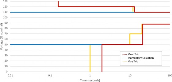
Figure 5 —Example low and high-voltage ride-through curves
Table 51 —Example low and high-voltage ride-through curve values
Curve | Points |
LV must trip | (2, 0), (2, 50), (21, 50), (21, 88), (100, 88) |
LV momentary cessation | (0, 50), (1.5, 50) |
LV may trip | (1, 0), (1, 50), (10, 50), (10, 70), (20, 70), (20, 88), (100, 88) |
HV must trip | (0.16, 130), (0.16, 120), (13, 120), (13, 110), (100, 110) |
HV momentary cessation | (0, 110), (13, 110) |
HV may trip | (0.16, 130), (0.16, 120), (12, 120), (12, 110), (100, 110) |
Figure 6 shows an example of frequency must trip and may trip curves, and Table 52 shows the specific values that would comprise the curve settings.
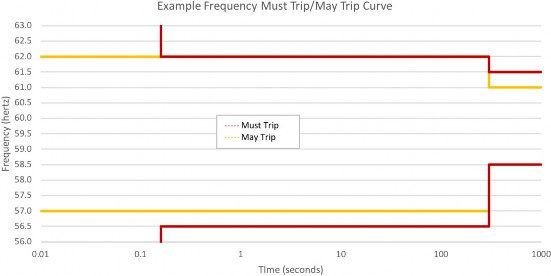
Figure 6 —Example low and high-frequency ride-through curves
Table 52 —Example low and high-frequency ride-through curve values
Curve | Points |
LF must trip | (0.16, 0), (0.16, 56.5), (300, 56.5), (300, 58.5), (1000, 58.5) |
LF may trip | (0, 57), (300, 57) |
HF must trip | (0.16, 63), (0.16, 62), (300, 62), (300, 61.5), (1000, 61.5) |
HF may trip | (0, 62), (300, 62), (300, 61), (1000, 61) |
10.10.4.4 DER info resources
10.10.4.4.1 Introduction
A DER MAY be modeled as one or more DER client instances. For example, a device that consists of a solar inverter with attached storage may be modeled as separate or combined generation and storage DERs, depending on the complexity of the device’s local control interface. The DER resource exposes the capability limits of a specific distributed energy resource, as well as basic settings, status, and availability. A DER client SHOULD store these resources locally.
The currently executing DERProgram SHALL be referenced by the DER’s CurrentDERProgramLink. This DERProgram instance SHOULD reference local copies of the active DERControl and DERCurves.
10.10.4.4.2 DERCapability
The DER resource exposes the capabilities of a specific distributed energy resource, referred to as its nameplate ratings. Ratings are read-only values established by the DER manufacturer by design or manufactured configuration, for instance, the continuous delivered active power rating capability in watts (rtgMaxW), and are available by reading the DERCapability resource.
10.10.4.4.3 DERSettings
The DERSettings resource provides a means to adjust the operating limits of a DER device as established by its nameplate ratings. For example, the active power output (setMaxW) may be reduced or increased as a function of attached photovoltaic panels, condition of the equipment, season of the year, or intended use, subject to the maximum limit by rtgMaxW. It should be noted that DERSettings are not likely to be updated by a remote party (such as a utility), but rather locally by, for example, an installer.
The basic settings also include configuration settings related to a specific installation such as setVRef, the nominal voltage at the point of common coupling; setVRefOfs, the voltage difference from the point of common coupling to the electrical connection point of the inverter; and the set point for the nominal frequency. Each rating value in a DER’s DERCapability instance MAY have a corresponding setting value in its DERSettings instance (which equals the rating value by default). A modified rating SHALL have a corresponding setting.
10.10.4.4.4 DERStatus
The DER resource references a DERStatus instance that contains basic operational status attributes for the DER device. Information such as accumulated generation readings SHOULD be made available by a sub- meter referenced by the DER’s AssociatedUsagePointLink.
10.10.4.4.5 DERAvailability
The DERAvailability object is used by client devices to report their availability to deliver reserve active and reactive power. It MAY also be exposed instead by devices that are able to report this information on behalf of other devices. Duration attributes MAY be provided to indicate how long the generation can be sustained.
10.10.5 DER client device requirements
DER device architectures are expected to vary widely. Therefore, minimum required functionality is based on DER type. A DER instance SHOULD be as simple as possible, but no simpler. For example, if a generator type DER can deliver reactive power and supports fixed var control mode, then it must include rtgMaxVar and setMaxVar.
If there is a significant difference between delivered and received var capability, then the DER MAY also include rtgMaxVarNeg and setMaxVarNeg or use rtgMaxVar to specify a common (minimum) rating for both delivered and received var. Similarly, if a device includes attached storage and the charging and discharging mode rating limits differ significantly, then the device can be modeled as separate DERs.
Each unique DER instance SHALL link to a DERCapability instance that SHALL contain type, modesSupported, and rtgMaxW attributes. The type attribute determines which additional modes and attributes are required as shown in Table 53 and Table 54.
Table 53 and Table 54 are interpreted as follows. If the optionality key in the column Opt1 is “M” (mandatory), then the DER SHALL support the control mode(s) listed under modesSupported; if the key is “R” (recommended), then the DER SHOULD support the listed control mode; if the key is “O” (optional), then the DER MAY support the listed control mode.
If the optionality key in the column Opt2 is “M” (mandatory), then the DER SHALL include the attribute(s) listed in the column Related attribute(s); if the key is “R” (recommended), then the DER SHOULD support the listed attribute; if the key is “O” (optional), then the DER MAY support the listed attribute.
If multiple modes are listed in a given entry, then support for any one of them meets the requirement. Each mode will then be individually listed together with its required attributes. If multiple attributes are listed in a given entry, then support for any one of them meets the requirement. For example, a storage DER that supports only charging (e.g., a PEV) may choose to omit rtgMaxChargeRateW and expose its maximum charging rate via the rtgMaxW attribute. However, if a storage DER also supports discharge mode, then it MUST use rtgMaxChargeRateW to expose its charging rate and MAY use either rtgMaxDischargeRateW (if the DER supports simultaneous generation and discharge) or rtgMaxW to expose its maximum discharging rate.
Table 53 —Modes and attributes for generator type DERs
Opt1 | modesSupported | Opt2 | Related attribute(s) | Notes |
M | 20: Maximum Active Power | M | rtgMaxW/setMaxW | Continuous active power output (includes maximum discharge rate if combined generator/storage type) |
O | rtgMaxVA/setMaxVA | Continuous apparent power out | ||
M | 24: Volt-Watt | |||
R | 6: Fixed var or 4 or 5: Fixed PF | |||
6: Fixed var | M | rtgMaxVar/setMaxVar | If Fixed Var mode is supported, then Volt-Var mode SHOULD be supported | |
O | rtgMaxVarNeg/ setMaxVarNeg | SHOULD be included if received and delivered var differ significantly | ||
4 or 5: Fixed PF | M | rtgMinPFOverExcited/ setMinPFOverExcited | If Fixed PF mode is supported, then Watt-PF mode SHOULD be supported | |
O | rtgMinPFUnderExcited/ setMinPFUnderExcited | SHOULD be included if received and delivered var differ significantly |
Table 54 —Modes and attributes for storage type DERs
Opt1 | modesSupported | Opt2 | Related attribute(s) | Notes |
M | 0: Charge mode | M | rtgMaxChargeRateW/ setMaxChargeRateW or rtgMaxW/setMaxW | rtgMaxChargeRateW is “M” if Discharge mode is supported |
M | rtgMaxWh or rtgMaxAh | Storage capacity | ||
O | 1: Discharge mode | M | rtgMaxChargeRateW/ setMaxChargeRateW | |
M | rtgMaxDischargeRateW/ setMaxDischargeRateW or rtgMaxW/setMaxW | rtgMaxDischargeRateW is “M” if combined generator/storage |
Storage type DERs include DERType 80 (other storage system), 81, 82, and 83 (combined PV and storage).
10.10.6 LogEvents
Table 55 —Distributed energy resources LogEvents
LogEvent name | LogEvent code | LogEvent description |
DER_FAULT_OVER_CURRENT | 0x00 | SHOULD be generated when a fault occurs (requiring an action such as a shutdown or restart) due to overcurrent |
DER_FAULT_OVER_CURRENT_RTN | 0x01 | SHOULD be generated when a fault due to overcurrent clears |
DER_FAULT_OVER_VOLTAGE | 0x02 | SHOULD be generated when a fault occurs (requiring an action such as a shutdown or restart) due to over voltage |
DER_FAULT_OVER_VOLTAGE_RTN | 0x03 | SHOULD be generated when a fault due to over voltage clears |
DER_FAULT_UNDER_VOLTAGE | 0x04 | SHOULD be generated when a fault occurs (requiring an action such as a shutdown or restart) due to under voltage |
DER_FAULT_UNDER_VOLTAGE_RTN | 0x05 | SHOULD be generated when a fault due to under voltage clears |
DER_FAULT_OVER_FREQUENCY | 0x06 | SHOULD be generated when a fault occurs (requiring an action such as a shutdown or restart) due to over frequency |
DER_FAULT_OVER_FREQUENCY_RTN | 0x07 | SHOULD be generated when a fault due to over frequency clears |
DER_FAULT_UNDER_FREQUENCY | 0x08 | SHOULD be generated when a fault occurs (requiring an action such as a shutdown or restart) due to under frequency |
DER_FAULT_UNDER_FREQUENCY_RTN | 0x09 | SHOULD be generated when a fault due to under frequency clears |
DER_FAULT_VOLTAGE_IMBALANCE | 0x0A | SHOULD be generated when a fault occurs (requiring an action such as a shutdown or restart) due to a voltage imbalance |
DER_FAULT_VOLTAGE_IMBALANCE_RTN | 0x0B | SHOULD be generated when a fault due to a voltage imbalance clears |
DER_FAULT_CURRENT_IMBALANCE | 0x0C | SHOULD be generated when a fault occurs (requiring an action such as a shutdown or restart) due to a current imbalance |
DER_FAULT_CURRENT_IMBALANCE_RTN | 0x0D | SHOULD be generated when a fault due to a current imbalance clears |
DER_FAULT_EMERGENCY_LOCAL | 0x0E | SHOULD be generated when a fault occurs (requiring an action such as a shutdown or restart) due to a local emergency |
DER_FAULT_EMERGENCY_LOCAL_RTN | 0x0F | SHOULD be generated when a fault due to a local emergency clears |
DER_FAULT_EMERGENCY_REMOTE | 0x10 | SHOULD be generated when a fault occurs (requiring an action such as a shutdown or restart) due to a remote emergency |
DER_FAULT_EMERGENCY_REMOTE_RTN | 0x11 | SHOULD be generated when a fault due to a remote emergency clears |
DER_FAULT_LOW_POWER_INPUT | 0x12 | SHOULD be generated when a fault occurs (requiring an action such as a shutdown or restart) due to low input power |
DER_FAULT_LOW_POWER_INPUT_RTN | 0x13 | SHOULD be generated when a fault due to low input power clears |
DER_FAULT_PHASE_ROTATION | 0x14 | SHOULD be generated when a fault occurs (requiring an action such as a shutdown or restart) due to phase rotation |
DER_FAULT_PHASE_ROTATION_RTN | 0x15 | SHOULD be generated when a fault due to phase rotation clears |